22
GB
Installation
!
Before operating your new appliance please read this instruction booklet
carefully. It contains important information for safe use, installation and care
of the appliance.
!
Please keep these operating instructions for future reference. Pass them on
to possible new owners of the appliance.
Positioning
!
Keep packaging material out of the reach of children. It can become a choking
or suffocation hazard (see Precautions and tips).
!
The appliance must be installed by a qualified professional according to the
instructions provided. Incorrect installation may cause harm to people and
animals or may damage property.
!
This unit may be installed and used only in permanently ventilated rooms
in accordance with current national regulations. The following requirements
must be observed:
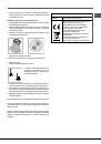
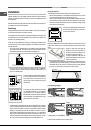
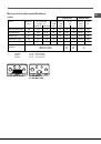
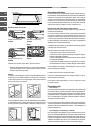
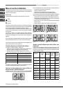
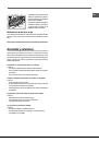
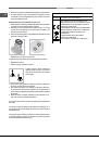
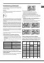
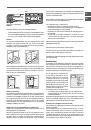
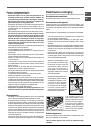
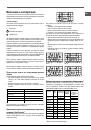
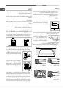
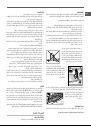
• The room must be equipped with an air extraction system that expels
any combustion fumes. This may consist of a hood or an electric fan that
automatically starts each time the appliance is switched on.
In a chimney stack or branched flue.
(exclusively for cooking appliances)
Directly to
the Outside
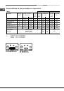
• The room must also allow proper air circulation, as air is needed for
combustion to occur normally. The flow of air must not be less than 2 m
3
/h
per kW of installed power.
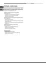
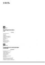
The air circulation system may take air directly
from the outside by means of a pipe with an
inner cross section of at least 100 cm
2
; the
opening must not be vulnerable to any type
of blockages.
The system can also provide the air needed
for combustion indirectly, i.e. from adjacent
rooms fitted with air circulation tubes as
described above. However, these rooms must
not be communal rooms, bedrooms or rooms
that may present a fire hazard.
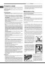
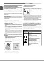
• Liquid petroleum gas sinks to the floor as it is heavier than air. Therefore,
rooms containing LPG cylinders must also be equipped with vents to allow
gas to escape in the event of a leak. As a result LPG cylinders, whether
partially or completely full, must not be installed or stored in rooms or
storage areas that are below ground level (cellars, etc.). It is advisable to
keep only the cylinder being used in the room, positioned so that it is not
subject to heat produced by external sources (ovens, fireplaces, stoves,
etc. ) which could raise the temperature of the cylinder above 50°C.
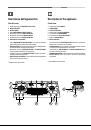
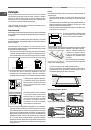
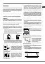
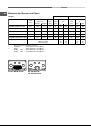
A
Examples of
ventilation holes
for comburant air.
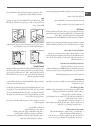
Enlarging the ventilation slot
between window and floor.
Adjacent
Room
Room to be
Vented
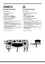
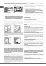
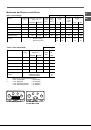
Fitting the appliance
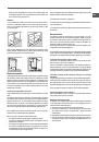
The following precautions must be taken when installing the hob:
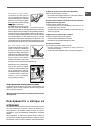
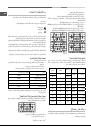
• Kitchen cabinets adjacent to the appliance and taller than the top of the
hob must be at least 600 mm from the edge of the hob.
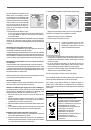
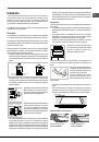
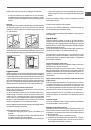
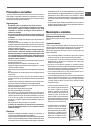
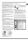
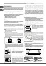
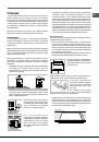
• Hoods must be installed according to their relative installation instruction
manuals and at a minimum distance of 650 mm from the hob (see figure).
• Place the wall cabinets adjacent to the hood at a minimum height of 420
mm from the hob (see figure).
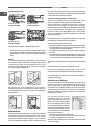
If the hob is installed beneath a wall cabinet,
the latter must be situated at a minimum of
700 mm above the hob.
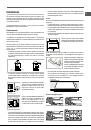
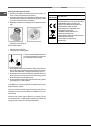
Before the installation remove the grids and burners from the hob and turn it
upside down, making sure you don’t damage the thermocouples and spark
plugs.
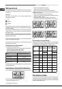
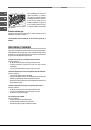
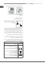
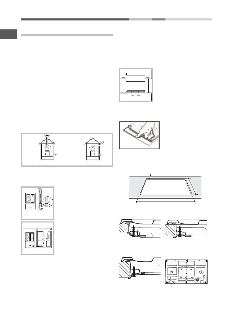
Apply the seals that come with the
appliance along the outer edges of
the hob to prevent any passage of air,
humidity and water (see Figure).
For proper application make sure the
surfaces to be sealed are clean, dry and
free of any grease/oil.
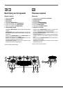
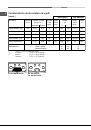
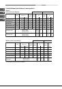
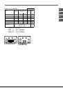
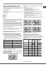
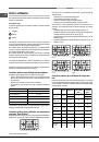
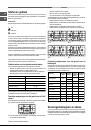
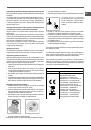
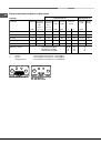
• The installation cavity should have the dimensions indicated in the figure.
Fastening hooks are provided, allowing you to fasten the hob to tops that
are between 20 and 40 mm thick. To ensure the hob is securely fastened
to the top, we recommend you use all the hooks provided.
475 mm.
835 mm.
min. 55 mm.
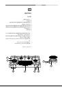
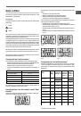
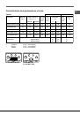
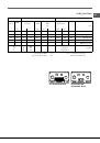
Hook fastening diagram
Hooking position for top
H=20mm
Hooking position for top
H=30mm
Front
Hooking position for top
H=40mm
Back
!
Use the hooks contained in the “accessory pack”.
600mm min.
420mm min.
650mm min.