GB
23
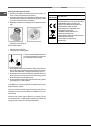
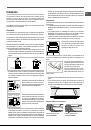
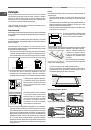
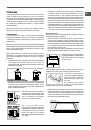
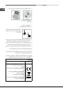
• Where the hob is not installed over a built-in oven, a wooden panel must
be installed as insulation. This must be placed at a minimum distance of
20 mm from the lower part of the hob.
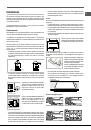
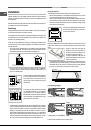
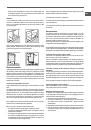
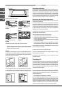
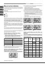
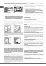
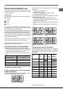
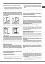
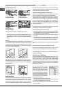
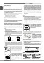
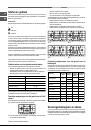
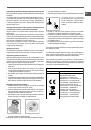
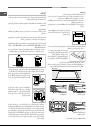
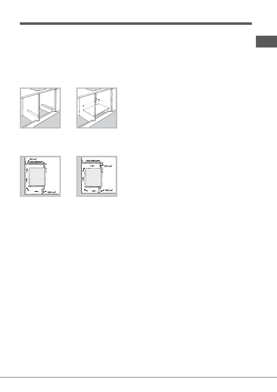
Ventilation
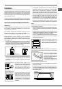
To ensure adequate ventilation, the back panel of the cabinet must be
removed. It is advisable to install the oven so that it rests on two strips of
wood, or on a completely flat surface with an opening of at least 45 x 560
mm (see diagrams).
560 mm
.
45 mm.
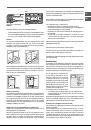
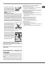
Where a hob is installed above an oven without a forced ventilation cooling
system, adequate ventilation must be provided inside the cabinet by means
of air holes through which air can pass (see figure).
Electrical connection
Hobs equipped with a three-pole power supply cable are designed to operate
with alternating current at the voltage and frequency indicated on the data
plate (this is located on the lower part of the appliance). The earth wire in the
cable has a green and yellow cover. If the appliance is to be installed above
a built-in electric oven, the electrical connection of the hob and the oven must
be carried out separately, both for electrical safety purposes and to make
extracting the oven easier.
Connecting the supply cable to the mains
Install a standardised plug corresponding to the load indicated on the data
plate.
The appliance must be directly connected to the mains using an omnipolar
circuit-breaker with a minimum contact opening of 3 mm installed between the
appliance and the mains. The circuit-breaker must be suitable for the charge
indicated and must comply with current electrical regulations (the earthing
wire must not be interrupted by the circuit-breaker). The supply cable must
not come into contact with surfaces with temperatures higher than 50°C.
!
The installer must ensure that the correct electrical connection has been
made and that it is compliant with safety regulations.
Before connecting to the power supply, make sure that:
• The appliance is earthed and the plug is compliant with the law.
• The socket can withstand the maximum power of the appliance, which is
indicated on the data plate.
• The voltage is in the range between the values indicated on the data plate.
• The socket is compatible with the plug of the appliance. If the socket is
incompatible with the plug, ask an authorised technician to replace it. Do
not use extension cords or multiple sockets.
!
Once the appliance has been installed, the power supply cable and the
electrical socket must be easily accessible.
!
The cable must not be bent or compressed.
!
The cable must be checked regularly and replaced by authorised technicians
only (see Assistance).
!
The manufacturer declines any liability should these safety measures not
be observed.
Gas connection
The appliance should be connected to the main gas supply or to a gas
cylinder in compliance with current national regulations. Before carrying out
the connection, make sure the cooker is compatible with the gas supply you
wish to use. If this is not the case, follow the instructions indicated in the
paragraph “Adapting to different types of gas.”
When using liquid gas from a cylinder, install a pressure regulator which
complies with current national regulations.
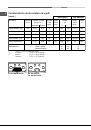
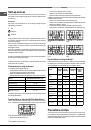
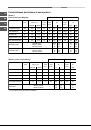
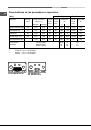
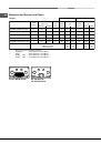
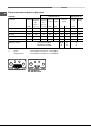
!
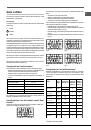
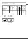
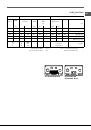
Check that the pressure of the gas supply is consistent with the values indicated
in Table 1 (“Burner and nozzle specifications”). This will ensure the safe operation
and longevity of your appliance while maintaining efficient energy consumption.
Connection with a rigid pipe (copper or steel)
!
Connection to the gas system must be carried out in such a way as not to
place any strain of any kind on the appliance.
There is an adjustable L-shaped pipe fitting on the appliance supply ramp
and this is fitted with a seal in order to prevent leaks. The seal must always
be replaced after rotating the pipe fitting (seal provided with appliance). The
gas supply pipe fitting is a threaded 1/2 gas cylindrical male attachment.
Connecting a flexible jointless stainless steel pipe to a threaded
attachment
The gas supply pipe fitting is a threaded 1/2 gas cylindrical male attachment.
These pipes must be installed so that they are never longer than 2000 mm
when fully extended. Once connection has been carried out, make sure that
the flexible metal pipe does not touch any moving parts and is not compressed.
!
Only use pipes and seals that comply with current national regulations.
Checking the tightness of the connection
!
When the installation process is complete, check the pipe fittings for leaks
using a soapy solution. Never use a flame.
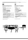
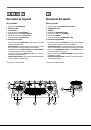
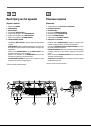
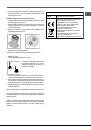
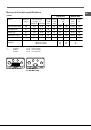
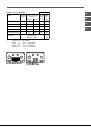
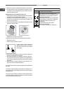
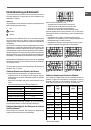
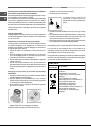
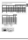
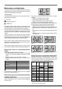
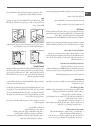
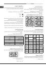
Adapting to different types of gas
To adapt the hob to a different type of gas other than default type (indicated
on the rating plate at the base of the hob or on the packaging), the burner
nozzles should be replaced as follows:
1. Remove the hob grids and slide the burners off their seats.
2. Unscrew the nozzles using a 7 mm socket spanner, and replace them
with nozzles for the new type of gas (see table 1 “Burner and nozzle
characteristics”).
3. Reassemble the parts following the above procedure in the reverse order.
4. Once this procedure is finished, replace the old rating sticker with one
indicating the new type of gas used. Sticker are available from any of our
Service Centres.