
20
© 2001- 2011 D-Link Corporation. All Rights Reserved.
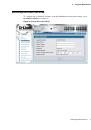
Configuration Guide
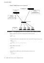
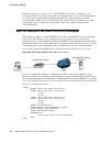
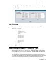
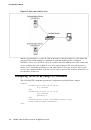
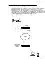
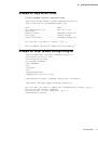
Starting the Switch
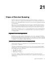
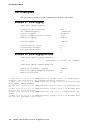
1. Make sure that the switch console port is connected to a VT100 terminal or a VT100 ter-
minal emulator via the RS-232 crossover cable.
2. Locate an AC power receptacle.
3. Deactivate the AC power receptacle.
4. Connect the switch to the AC receptacle.
5. Activate the AC power receptacle.
When the power is turned on with the local terminal already connected, the switch goes
through a power-on self-test (POST). POST runs every time the switch is initialized and
checks hardware components to determine if the switch is fully operational before completely
booting. If POST detects a critical problem, the startup procedure stops. If POST passes
successfully, a valid executable image is loaded into RAM. POST messages are displayed on
the terminal and indicate test success or failure. The boot process runs for approximately 60
seconds.
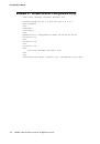
Initial Configuration
NOTE:
The initial simple configuration procedure is based on the following assump-
tions:
•
The switch was not configured before and is in the same state as when you received it.
•
The switch booted successfully.
•
The console connection was established and the console prompt appears on the screen of a
VT100 terminal or terminal equivalent.
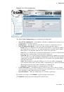
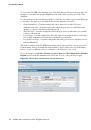
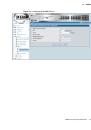
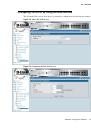
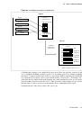
The initial switch configuration is performed through the console port. After the initial
configuration, you can manage the switch either from the already-connected console port or
remotely through an interface defined during the initial configuration.
NOTE:
The switch is not configured with a default user name and password.
NOTE:
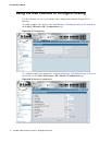
All of the settings below are necessary to allow the remote management of the
switch through Telnet (Telnet client) or HTTP (Web browser).
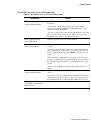
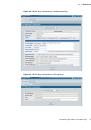
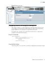
Before setting up the initial configuration of the switch, obtain the following information from
your network administrator:
•
The IP address to be assigned to the management interface through which the switch is
managed.
•
The IP subnet mask for the network.
•
The IP address of the default gateway.
 1
1
 2
2
 3
3
 4
4
 5
5
 6
6
 7
7
 8
8
 9
9
 10
10
 11
11
 12
12
 13
13
 14
14
 15
15
 16
16
 17
17
 18
18
 19
19
 20
20
 21
21
 22
22
 23
23
 24
24
 25
25
 26
26
 27
27
 28
28
 29
29
 30
30
 31
31
 32
32
 33
33
 34
34
 35
35
 36
36
 37
37
 38
38
 39
39
 40
40
 41
41
 42
42
 43
43
 44
44
 45
45
 46
46
 47
47
 48
48
 49
49
 50
50
 51
51
 52
52
 53
53
 54
54
 55
55
 56
56
 57
57
 58
58
 59
59
 60
60
 61
61
 62
62
 63
63
 64
64
 65
65
 66
66
 67
67
 68
68
 69
69
 70
70
 71
71
 72
72
 73
73
 74
74
 75
75
 76
76
 77
77
 78
78
 79
79
 80
80
 81
81
 82
82
 83
83
 84
84
 85
85
 86
86
 87
87
 88
88
 89
89
 90
90
 91
91
 92
92
 93
93
 94
94
 95
95
 96
96
 97
97
 98
98
 99
99
 100
100
 101
101
 102
102
 103
103
 104
104
 105
105
 106
106
 107
107
 108
108
 109
109
 110
110
 111
111
 112
112
 113
113
 114
114
 115
115
 116
116
 117
117
 118
118
 119
119
 120
120
 121
121
 122
122
 123
123
 124
124
 125
125
 126
126
 127
127
 128
128
 129
129
 130
130
 131
131
 132
132
 133
133
 134
134
 135
135
 136
136
 137
137
 138
138
 139
139
 140
140
 141
141
 142
142
 143
143
 144
144
 145
145
 146
146
 147
147
 148
148
 149
149
 150
150
 151
151
 152
152
 153
153
 154
154
 155
155
 156
156
 157
157
 158
158
 159
159
 160
160
 161
161
 162
162
 163
163
 164
164
 165
165
 166
166
 167
167
 168
168
 169
169
 170
170
 171
171
 172
172
 173
173
 174
174
 175
175
 176
176
 177
177
 178
178
 179
179
 180
180
 181
181
 182
182
 183
183
 184
184
 185
185
 186
186
 187
187
 188
188
 189
189
 190
190
 191
191
 192
192