The operator should remain alert and keep the milling
head apart from all objects during operation.
When the milling operation has been completed,
locking lever should be operated so that the machine
returns to its upper starting position.
The motor must be allowed to come to completely stop
before being put to one side between uses.
The milling heads should be protected from impacts
and knocks.
The milling heads should not be touched after use
because they could cause serious burns.
BRIEF DESCRIPTION
This machine is designed for use with rotary milling heads
for milling slots, edges, profiles and rough-edged holes,
from a firm base, in wood, synthetic and light construction
materials, and for milling operation with a copier.
By employing the correct milling heads and using slow
speeds, non-ferrous metals may also be milled.
BEFORE USING THIS TOOL
Make sure the mains voltage is correct: it must be the
same as that on the specification label. Machines with
230-V can also be connected to a 220-V mains supply.
Press the locking button
A
, and squeeze the trigger in
the on/off switch
A1
. When the on/off switch is released,
the machine stops.
For safety reasons, it is not possible to lock On/Off
switch
A1
, instead it has to be pressed while the ma-
chine is being used.
Speed adjustments. Constant electronic performance
The control electronics allow continuous pre-setting of
the revolutions and impact frequency to adapt the ma-
chine to the type of material to be worked on. Adjust-
ment is made using the speed adjustment switch
L
,
which has 6 positions to regulate the speed.
The higher the number, the greater the speed and
impact energy. The range of settings from “1” (low
power) to “6” (full power) makes the tool very flexible
and adaptable to different applications.
The constant speed control maintains the pre-set num-
ber of revolutions and impact frequency.
Check the speed adjustment label for the desired work-
ing speed.
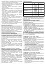
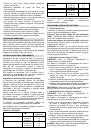
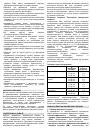
Revolutions table
Material
milling
head
Revolution
stages
Hard wood (beech)
4-10 mm
12-20 mm
22-40 mm
5-6
3-4
1-2
Soft wood (pine)
4-10 mm
12-20 mm
22-40 mm
5-6
3-6
1-3
Plywood boards
4-10 mm
12-20 mm
22-40 mm
3-6
2-4
1-3
Synthetic materials
4-15 mm
16-40 mm
2-3
1-2
Aluminum 4-15
mm
16-40 mm
1-2
1
The values in this table are for guideline purposes only.
The required revolutions will depend on the material and
working conditions. It is recommended that these be
established by carrying out tests with the machine.
MILLING HEAD SELECTION AND INSTALLATION
1.1. Milling head selection
Depending on the materials to be worked, the following
milling head qualities may be selected:
High-performance, fast-cutting steel milling heads
(HSS):
suitable for soft materials, such as soft woods
and plastic.
Milling heads with hard metal blades (HM):
suitable
hard and abrasive materials, such as hard woods and
aluminium.
WARNING!
The milling heads that are employed must
be officially approved in accordance with the maximum
revolutions defined for the respective tools. The milling
head shaft diameter should match the inside diameter of
the tool-holder (locking clip).
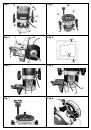
1.2. Assembly of the milling head option 1 (Fig.8)
WARNING!
The mains cable must be removed from the
socket before any adjustments are made to the machine.
It is recommended that protective gloves be worn when
installing or removing milling heads.
1. To assemble the milling head, press the blocking
button of the clip-holder shaft
B
matching up the
pivot with the axis groove to avoid it from spinning.
2. A 22-mm spanner should be used to loosen clip
fixing nut
D
in an anticlockwise direction.
3. Insert the milling head so that the shaft enters the
clip by a minimum of 20 mm (shaft length).
4. Tighten the clip fixing nut
D
with the spanner and
release the clip-carrier shaft support lever
B
.
PRECAUTION:
Do not tighten clip fixing nut
D
without a
milling head inserted into the clip.
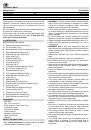
1.3. Assembly of the milling head 2 auto-block
WARNING!
The mains cable must be removed from the
socket before any adjustments are made to the machine.
It is recommended that protective gloves be worn when
installing or removing milling heads.
1. To assemble the milling head, move the fixing lever
H
, lower the machine to the maximum point and set
the fixing lever
H
, turn the clip-holder shaft matching
it up the axis groove with the blocking button
B
.
2. A spanner should be used to loosen clip fixing nut
D
in an anticlockwise direction.
3. Insert the milling head so that the shaft enters the
clip by a minimum of 20 mm (shaft length).
4. Tighten the clip fixing nut
D
with the spanner and
release the clip-carrier shaft support lever
B
.
PRECAUTION:
Do not tighten clip fixing nut
D
without a
milling head inserted into the clip.
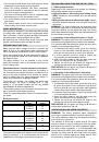
ADJUSTING MILLING OPERATION DEPTH
WARNING!
The milling operation depth adjustment
must only be performed with the machine switched off.
The milling operation depth may be adjusted according
to the work to be carried out.
The machine is fitted with a depth stop
E
, the upper
surface of which is used in conjunction with the gradu-
ated scale
Y
fine control of the milling operation depth.
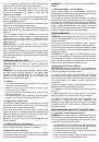
For deep cutting operations, it is recommended that
several passes be made, with a reduced chip thickness.
Operate the fixing lever
H
and slowly push the upper
section of the machine against the depth stop
E
. Lock
the machine by releasing the fixing lever
H
.