1.1.
Loosening the locking wing nut
G
will release the
depth stop
E
, facilitating simple stop adjustment.
Adjust the required depth using scale
Y
with the
depth adjustment handle
N
, tighten the locking wing
nut
G
, fine adjustment is obtained using the fine
adjustment handle
M
.
1.2.
The depth of the cut can also be adjusted with the
handle
C
, turning it clockwise to increase depth and
counter clockwise to reduce.
Fixing lever
H
should be pressed to immobilize the
machine at a determined working height.
To prevent running off-load, rotate the depth adjustment
handle
N
and
C
until the desired return distance is
obtained.
With the stepped stop
F
it is possible to perform the
milling operation in three stages. To start, adjust the
milling depth to the lowest position of stepped stop
F
.
Then the milling operation can be carried out at the
higher positions.
PRECAUTION:
For large diameter cuts, it is recom-
mended that the depth is set to minimum and to con-
tinue cutting in stages.
When commencing the work, the milling head should be
slowly entered until the desired depth is obtained and
then allowed to advance, always supporting the machine
with two hands.
OPERATING INSTRUCTIONS.
PRECAUTION:
The machine should always be
unplugged before making any adjustments to the
machine.
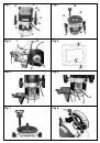
WARNING!
The actual milling operation should always
be made in the direction opposite to the milling head
rotation direction (according to Fig. 4). Advancing the
machine in the opposite direction could cause it to
rebound and lead to an accident.
1.1. Milling
1. The milling depth should be adjusted in accordance
with the previous description.
2. Switch on and place the machine over the work
piece, firmly held in place.
3. Carry out the milling operation with a uniform ad-
vancing movement.
4. On completing the milling operation, push the upper
section of the machine upwards and switch it off.
1.2. Milling with parallel stop
To install the parallel stop and with the guide rods in the
base plate
P
and held in place with the wing screws
V
according to the required measurement.
Once both wing screws
V
have been loosened, the
parallel stop can be re-adjusted using fine adjustment
S
.
Adjust the desired length with the divisions with inches
and millimeters marked on the side stop
I
.
Stop strip
T
may be used to increase the parallel stop
contact surface.
1.3. Milling with the copier bushing
Copy bushing
U
enables edges to be milled on the work-
piece in accordance with a pattern or template.
Installing the copier bushing
In order to use the copier bushing
U
, it must be installed
on the lower section of support plate
P
from above and
fixed in place with the screws.
WARNING!
It is essential to ensure correct installation
position.
1.4. Milling straight or profiled edges
When milling straight or profiled edges, without the
parallel stop, the milling head must be fitted with a guide
shaft or ball bearing (optional accessory).
The operating machine should be brought into contact
with the work-piece from the side, until the milling head
guide shaft or ball bearing is seated against the edge of
the work piece. The machine must be guided with both
hands, always perpendicular to the surface, along the
entire length of the work-piece edge. Excessive applied
pressure could damage the work-piece edge.
DUST EXTRACTION
WARNING!
Always make sure that the tool is switched
off and unplugged before fitting or removing any dust
extraction device.
Dust extraction keeps the workplace clean, prevents
dust build-up in the air and facilitates waste elimination.
These milling machines are fitted with adapter, which
can be coupled to a universal vacuum aspirator or other
dust suction device.
CAUTION:
A suction extractor should always be used
that has been designed in accordance with the applica-
ble directives in relation to dust emission when milling
wood. The flexible hoses of conventional vacuum clean-
ers fit directly onto the dust extraction nozzle.
Installing the dust suction adapter
PRECAUTION:
Before installing the suction adapter
K
,
press the fixing lever
H
so that the upper section of the
machine ascends to the upper position.
In order to install the dust suction adapter
K
, it should
be inserted in the square opening on the base plate
P
until it fits fully into place, and then fixed using the wing
screws
R
, which are located on both sides of the
adapter
K
.
In order to maintain optimum chip extraction, the suction
adapter
K
should be periodically cleaned.
The aspirator should be suitable for the material being
worked.
A special aspirator must be employed in those cases
where dry harmful or carcinogenic dust is produced.
In situations where prolonged wood operations are
performed or machines are used industrially with
materials that produce dust that is harmful to health,
the machine must be connected to a suitable external
aspiration device.
MILLING MACHINE ADAPTED TO A WORK TABLE
1.1. Assembly of the milling head (Fig.7)
WARNING!
The mains cable must be removed from the
socket before any adjustments are made to the machine.
It is recommended that protective gloves be worn when
installing or removing milling heads.
1. To assemble the milling head, turn the depth handle
W
until it stops, turn the clip-holder shaft to match up
the axis groove with the blocking button
B
.
2. A spanner should be used to loosen clip fixing nut
D
in an anticlockwise direction.
3. Insert the milling head so that the shaft enters the
clip by a minimum of 20 mm (shaft length).