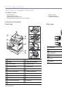
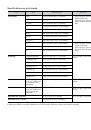
Installing accessories
|
85
5.
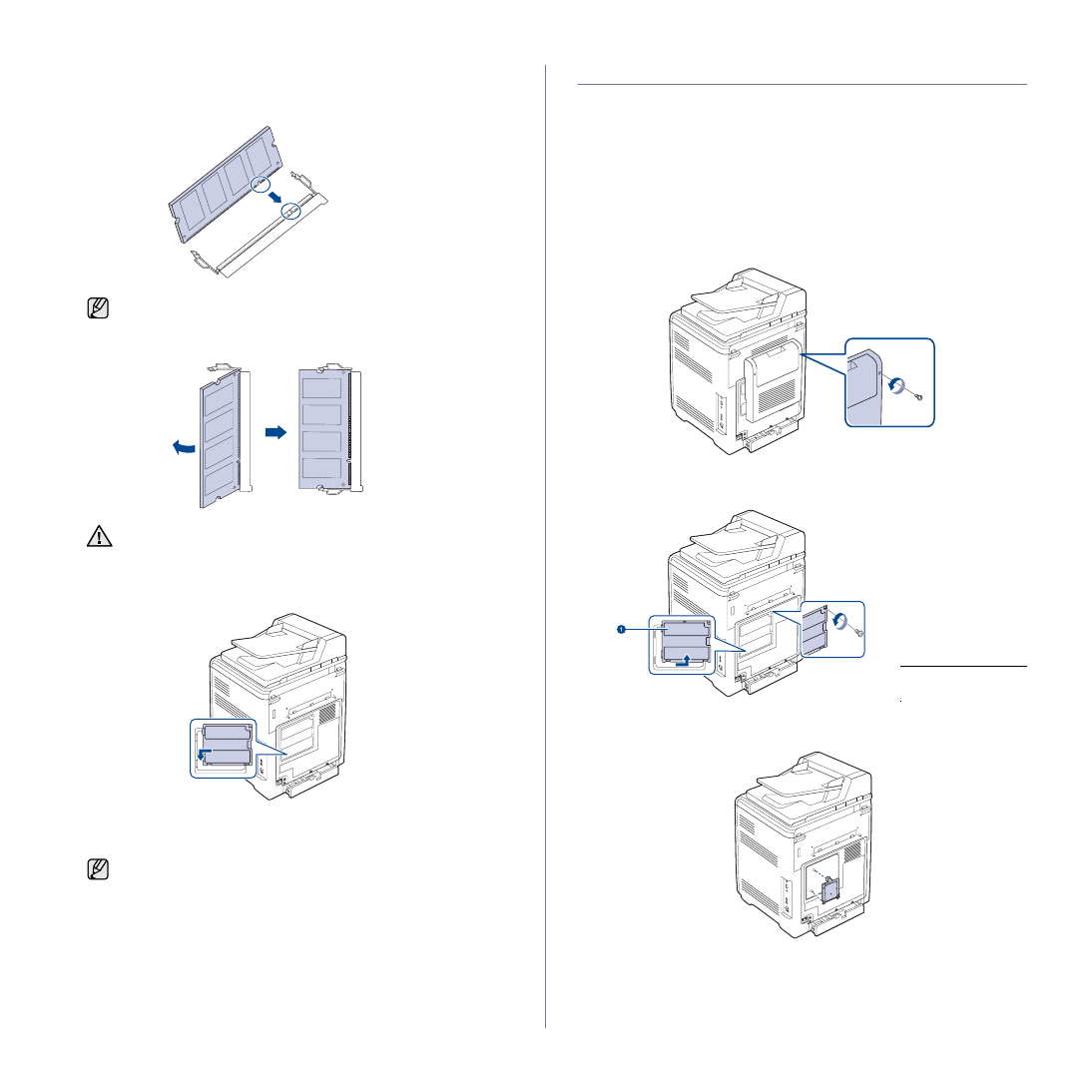
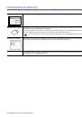
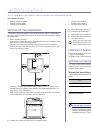
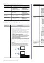
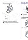
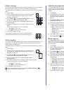
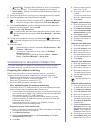
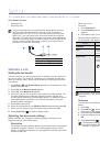
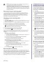
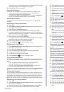
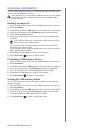
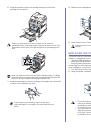
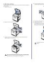
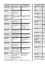
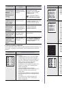
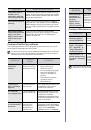
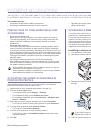
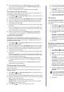
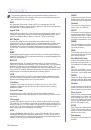
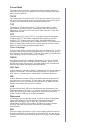
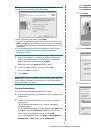
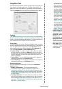
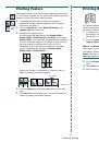
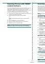
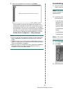
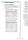
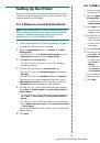
Holding the memory module by the edges, align the memory module on
the slot at about a 30-degree tilt. Ensure that the notches of the module
and the grooves on the slot fit each other.
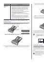
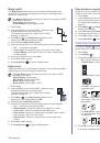
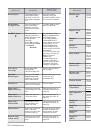
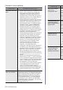
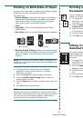
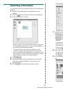
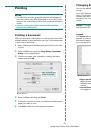
6.
Press the memory module into the slot with care until you hear a 'click'.
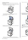
7.
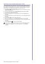
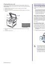
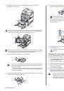
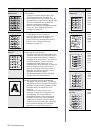
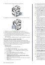
Replace the control board cover and fasten the cover with the screws.
8.
Replace the rear cover and fasten the cover with the screw.
9.
Reconnect the power cord and printer cable, and turn the printer on.
10.
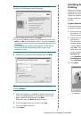
If you use the PS driver, you must activate the added memory in the PS
driver properties.
See "Activating the added accessories in printer properties" on page 84.
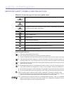
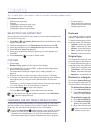
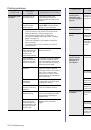
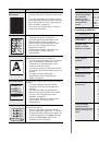
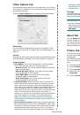
USING THE HARD DISK
Installing the hard disk allows the data from your computer to be sent to the
print queue of the printer hard disk. This decreases the workload of the
computer. You can also use various print features, such as storing a job in
the hard disk, proofing a job, and printing private documents.
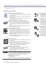
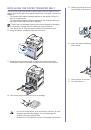
Installing the hard disk
For order information, see "Accessories" on page 83. Review the
precautions on page 84.
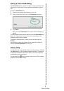
1.
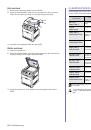
Turn the printer off and unplug all cables from the printer.
2.
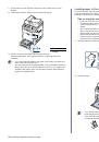
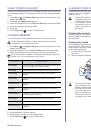
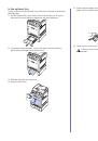
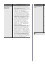
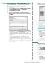
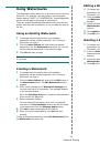
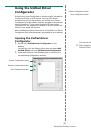
Release the screws and remove the rear cover.
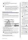
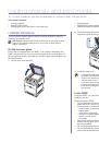
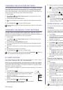
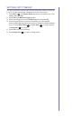
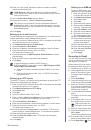
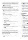
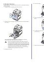
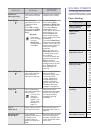
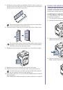
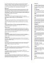
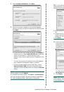
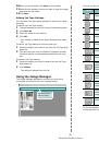
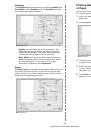
3.
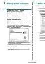
Open the control board cover. Release the screws, then lift up the cover
slightly and pull the cover to the right.
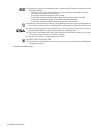
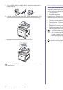
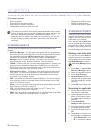
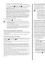
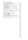
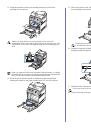
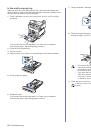
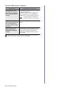
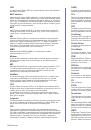
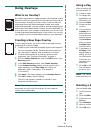
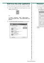
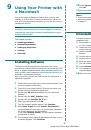
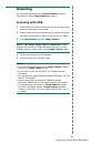
4.
Align the connector on the hard disk with the connector on the control
board. Push the hard disk in until it is latched into place
.
The notches and grooves illustrated above may not match those
on an actual memory module and its slot.
Do not press the memory module strongly or the module may be
damaged. If the module does not seem to fit into the slot properly,
carefully try the previous procedure again.
To release the memory module, pull the two tabs on the sides of
the slot outwards, then the module springs out.
1
control board
cover
 1
1
 2
2
 3
3
 4
4
 5
5
 6
6
 7
7
 8
8
 9
9
 10
10
 11
11
 12
12
 13
13
 14
14
 15
15
 16
16
 17
17
 18
18
 19
19
 20
20
 21
21
 22
22
 23
23
 24
24
 25
25
 26
26
 27
27
 28
28
 29
29
 30
30
 31
31
 32
32
 33
33
 34
34
 35
35
 36
36
 37
37
 38
38
 39
39
 40
40
 41
41
 42
42
 43
43
 44
44
 45
45
 46
46
 47
47
 48
48
 49
49
 50
50
 51
51
 52
52
 53
53
 54
54
 55
55
 56
56
 57
57
 58
58
 59
59
 60
60
 61
61
 62
62
 63
63
 64
64
 65
65
 66
66
 67
67
 68
68
 69
69
 70
70
 71
71
 72
72
 73
73
 74
74
 75
75
 76
76
 77
77
 78
78
 79
79
 80
80
 81
81
 82
82
 83
83
 84
84
 85
85
 86
86
 87
87
 88
88
 89
89
 90
90
 91
91
 92
92
 93
93
 94
94
 95
95
 96
96
 97
97
 98
98
 99
99
 100
100
 101
101
 102
102
 103
103
 104
104
 105
105
 106
106
 107
107
 108
108
 109
109
 110
110
 111
111
 112
112
 113
113
 114
114
 115
115
 116
116
 117
117
 118
118
 119
119
 120
120
 121
121
 122
122
 123
123
 124
124
 125
125
 126
126
 127
127
 128
128
 129
129
 130
130
 131
131
 132
132
 133
133
 134
134
 135
135
 136
136
 137
137
 138
138
 139
139
 140
140
 141
141
Инструкции и руководства похожие на DELL 2145cn