3 (E)
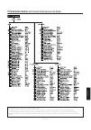
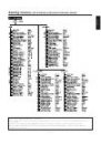
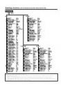
Contents
Introduction ....................................................................... 3
Accessories ...................................................................... 3
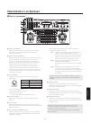
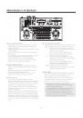
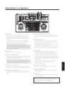
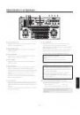
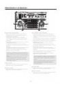
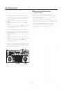
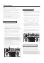
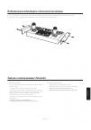
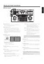
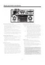
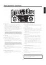
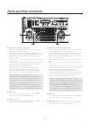
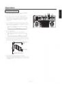
Parts and their functions ................................................. 4
Control panel ................................................................... 4
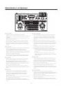
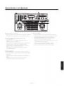
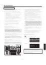
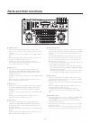
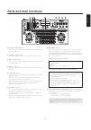
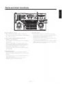
Rear connector panel .................................................... 11
Connections .................................................................... 14
Operation ......................................................................... 18
Turning on the power ..................................................... 18
Setting the camera model ............................................. 18
Ad justing the minimum start speed
of the pan/tilt head .................................................... 19
Adjusting the backlash compensation ........................... 19
Adjusting the minimum start speed of the lens zoom ... 20
Setting the travel range (limiters) of the pan/tilt head .... 20
Genlock adjustment ...................................................... 21
Total pedestal adjustment ............................................. 24
White balance adjustment ............................................. 25
Black balance adjustment ............................................. 26
Tracing memory settings ............................................... 27
Preset memory settings ................................................ 31
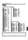
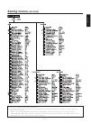
Setting menus ................................................................. 33
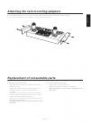
Attaching the rack mounting adapters ......................... 40
Replacement of consumable parts ............................... 40
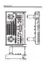
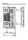
Appearance ..................................................................... 41
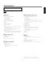
Specifications ................................................................. 42
Accessories
Rack mounting adapters (5U) ......................................... 2
Mounting screws (M48 mm) ........................................ 4
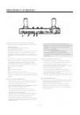
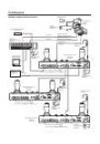
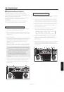
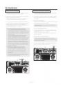
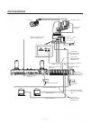
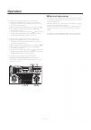
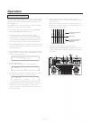
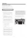
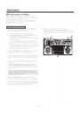
Introduction
This unit is a multi-function controller that controls the
pan/tilt head system (pan/tilt head and convertible
camera).
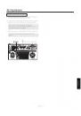
Up to 2 additional units may be attached to this unit,
allowing for control of the pan/tilt head system from
3 locations.
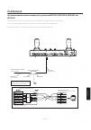
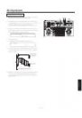
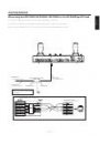
Please use a 10BASE-T straight cable (UTP category 5)
to connect to this unit.
4-pin XLR Inter Communication (INCOM)-use headsets
may be connected to communicate with this unit or an
external unit.
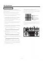
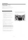
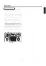
Up to 5 additional pan/tilt head systems may be
connected to this unit. The connection between the
pan/tilt head system and this unit may be extended up to
1000 meters when using AW-PH360, AW-PH350 or
AW-PH650 as the pan/tilt head.
The distance may be extended to 800 meters when using
other pan/tilt heads.
Use cable compensation unit AW-RC400 when using a
cable compensator for the video signal from the pan/tilt
head system.
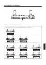
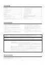
AW-PH300, AW-PH300A, AW-PH350, AW-PH360, AW-PH500, AW-PH600, AW-PH650
The camera function cannot be controlled when the AW-PH500 is used.
Pan/tilt heads
supported
Use the dedicated AC adapter AW-PS505A (sold separately) for the power supply.
Recommended
adapter
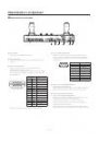
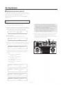
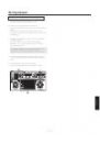
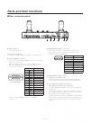
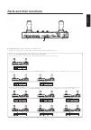
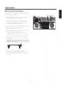
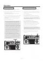
The operating mode may be switched by changing the settings of the ID Switch (see page 13) in the
back of this unit.
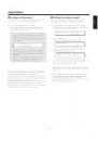
• Stand-alone Mode:
All of this unit’s functions may be used.
• Additional Panel Mode: The unit will operate as an additional panel when the AW-RP655 is operated
in Stand-alone Mode. Only the INCOM connector for INCOM headsets and
the TO CONTROL PANEL IN/OUT terminal may be used as connectors with
external units.
In this guide, “additional panel” will be used to describe the AW-RP655 set to Additional Panel
Mode.
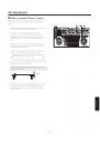
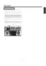
This unit will set the standard position for the operating lever (ZOOM lever, PAN/TILT lever,
FOCUS/IRIS dial) when the power is turned on and during OPERATE ON. Do not touch the operating
lever while the standard position setting is taking place.
Please contact a specialist when discarding this unit in consideration of the environment.
Caution