23 (E)
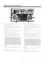
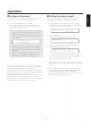
The subcarrier phase adjustment must be performed, when
composite signals have been set as the video input signals
and the pictures are to be switched by a video switcher or
other equipments.
This adjustment is not necessary when component signals
have been set as the video input signals.
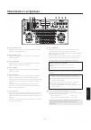
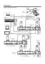
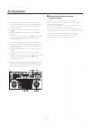
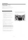
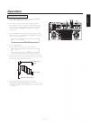
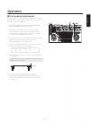
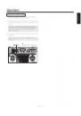
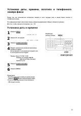
1. Select the pan/tilt head system using the CONTROL/
PREVIEW MONITOR OUT SEL button.
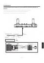
2. Connect the video switcher to the video signal
corresponding to the currently selected pan/tilt head
system (when using the cable compensation unit, the
corresponding Y/VIDEO OUT terminal) and the colour
monitor to the video switcher’s video output terminal.
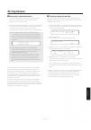
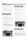
3. Press the MODE button to establish the BAR mode and
switch the output signals from the convertible camera to
colour bar signals.
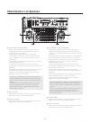
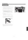
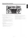
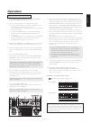
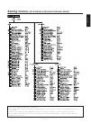
4. Press the MENU button, turn the menu setting control
(main), and set it so that the G/L SETTING item appears
at the top of the LCD panel.
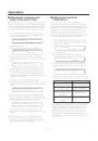
G/L SETTING
OK Key
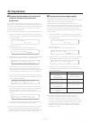
5. Press the OK button.
The following item appears on the LCD panel.
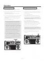
H PHASE
0
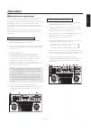
6. Turn the menu setting control (main), and set it so that
the following item appears on the LCD panel.
SC PHASE
COARSE:1 FINE: 0
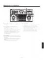
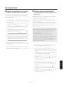
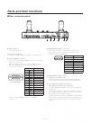
7. Output both the colour bar signals (signals from inside
the switcher or other equipments) serving as the
reference and the colour bar signals from the camera to
the colour monitor.
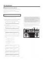
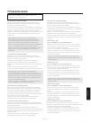
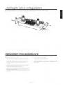
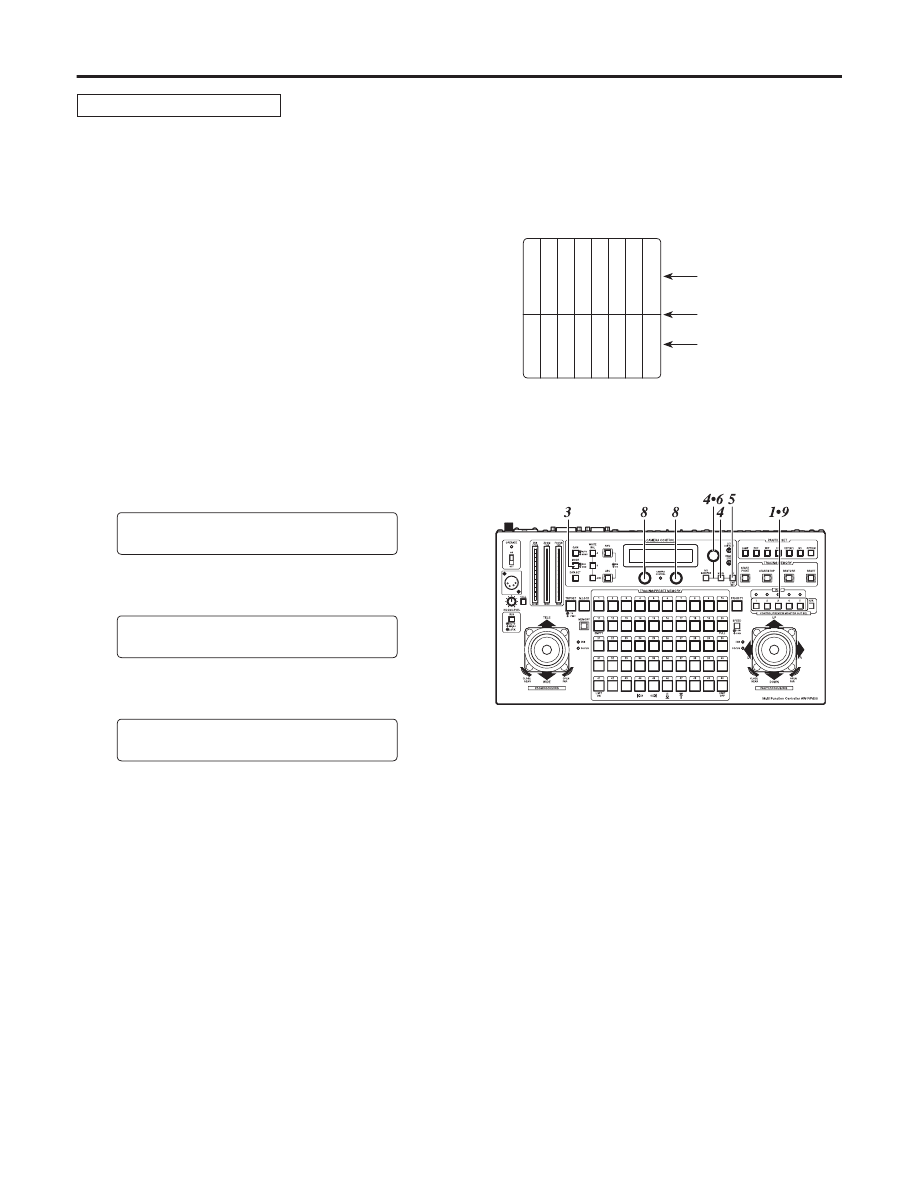
8. Align the phase of the colour bar signals from the
camera with the phase of the colour bar signals serving
as the reference.
Use the menu setting control (L) to adjust the phase in
90-degree increments and then the menu setting control
(R) to make fine adjustments.
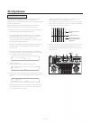
9. Select the next pan/tilt head system using the
CONTROL/PREVIEW MONITOR OUT SEL button, and
continue adjusting the subcarrier phase in each system
concerned.
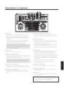
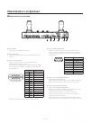
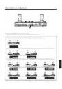
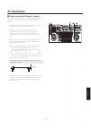
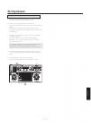
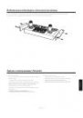
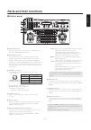
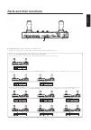
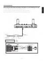
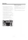
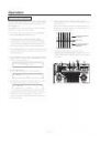
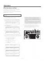
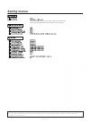
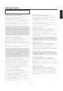
Subcarrier phase adjustment
White
Yello
w
Cy
an
Green
Magenta
Red
Blue
Blac
k
Colour bar signals from
the camera
Partition line
Colour bar signals from
the switcher or other
equipments
Operation