11 (E)
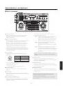
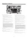
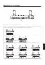
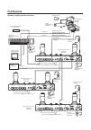
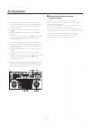
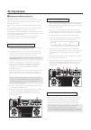
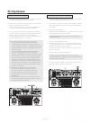
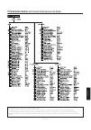
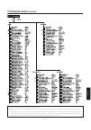
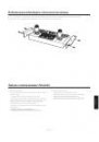
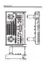
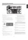
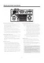
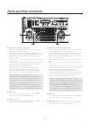
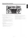
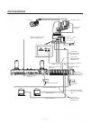
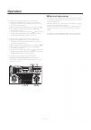
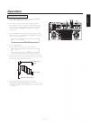
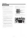
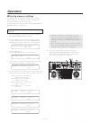
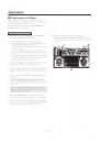
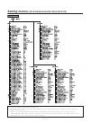
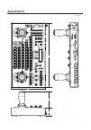
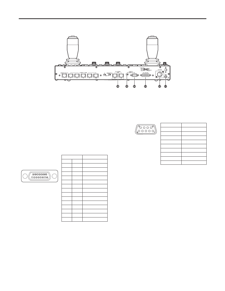
Rear connector panel
Parts and their functions
GND terminal
Use to ground the unit.
DC12V IN terminal
Connects the AW-PS505A AC adapter (sold separately).
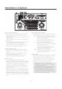
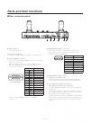
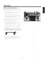
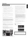
TALLY/INCOM connector
Connect this to the TALLY/INCOM connector on the video
switcher or other units.
When the TALLY connector is set to the GND level, the
TALLY lamp () lights. Do not apply a voltage in excess
of 5 V to this connector.
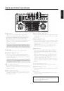
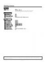
Pin No.
Signal Name
1
TALLY1
9
TALLY2
2
TALLY3
10
TALLY4
3
TALLY5
11
TALLY GND
4
–––
12
–––
5
–––
13
–––
6
MIC+
14
MIC–
7
INCOM GND
15
SP–
8
SP+
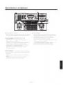
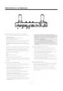
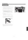
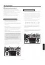
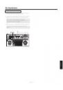
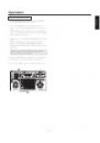
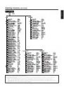
Connect a 4-wire INCOM system to the INCOM
connector.
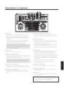
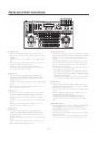
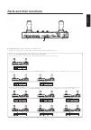
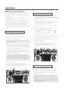
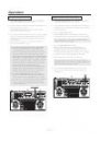
REMOTE/SERVICE connector
A personal computer or other external equipment is
connected here when a pan/tilt head system is to be
controlled by these equipments.
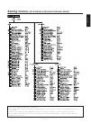
Pin No.
Signal Name
1
–––
2
RXD IN
3
TXD OUT
4
DTR
5
GND
6
DSR
7
RTS
8
CTS
9
–––
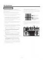
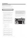
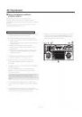
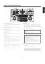
REMOTE/SERVICE switch
(Setting at shipment: N)
Function selection switch for the REMOTE/SERVICE
connector. Set the switch in the “N” position during use.
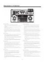
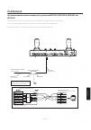
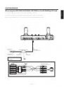
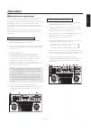
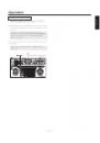
TO CONTROL PANEL IN terminal
TO CONTROL PANEL OUT terminal
Connects AW-RP655 (additional panel) set to Additional
Panel Mode.
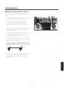
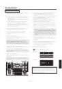
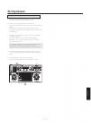
Connect the IN terminal of this unit to the OUT terminal
of the additional panel, or the OUT terminal of this unit to
the IN terminal of the additional panel.
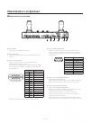
The MIC and SP connections for INCOM communication
are reversed for the IN terminal and OUT terminal. Do not
connect the IN terminals together or the OUT terminals
together.
Pin layout as seen from the
back of AW-RP655