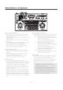
13 (E)
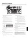
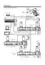
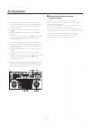
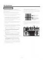
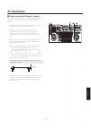
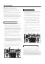
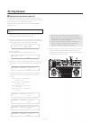
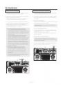
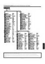
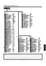
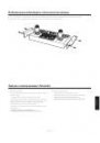
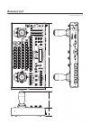
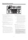
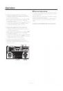
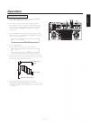
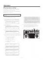
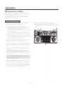
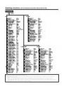
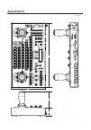
Parts and their functions
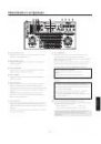
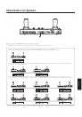
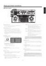
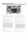
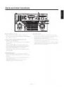
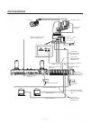
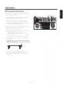
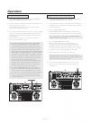
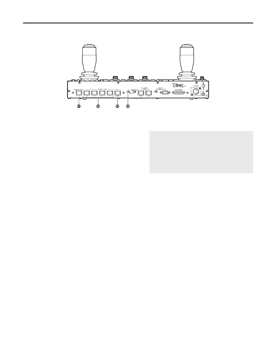
ID switch (Setting at shipment: MAIN)
Switch to set the operating mode for this unit.
Stand-alone Mode:
All of this unit’s functions may be used.
Additional Panel Mode:
The unit will operate as an additional panel when the
AW-RP655 is operated in Stand-alone Mode. Only the
INCOM connector for INCOM headsets and the TO
CONTROL PANEL IN/OUT terminal may be used as
connectors with external units.
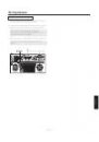
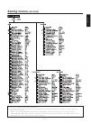
The operating mode is established when the power to
the unit is turned on. Before setting it, be absolutely sure
to turn off the power of the AC adapter that supplies the
power to the unit. Bear in mind that the power of the unit
cannot be turned off using the OPERATE switch.
MAIN:
Operates in Stand-alone Mode.
1/2:
Operates in Additional Panel Mode.
In the case of a system with 2 connected additional
panels, set each additional panel setting to a different
value.
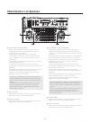
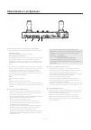
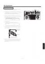
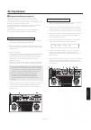
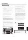
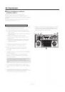
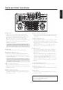
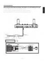
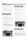
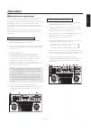
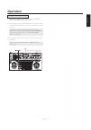
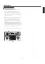
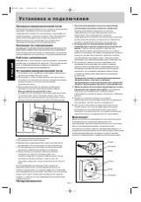
TO PAN/TILT HEAD 1/EXT terminal
• Functions as the pan/tilt head’s connection terminal 1
when the EXT CONTROL OUT is set to OFF on the
controller setting menu (see page 37).
Connect a 10BASE-T straight cable (equivalent to UTP
category 5) to the pan/tilt head’s IP/RP terminal.
May be extended up to a maximum of 1000 m.
Use the RS-232C/RS-422 converter and connect
to pan/tilt head’s RS-232C control terminal when
connecting to the AW-PH300, AW-PH300A, AW-PH500
or AW-PH600.
• Functions as the AW-DU600 dial up adapter’s connection
terminal when the EXT CONTROL OUT is set to ON on
the controller setting menu (see page 37).
Connect a 10BASE-T straight cable (equivalent to UTP
category 5) to the AW-DU600’s PAN/TILT CONTROL IN
terminal. May be extended up to a maximum of
1000 m.
For more details, refer to the operating instructions
of the dial up adapter AW-DU600. Use the following
terms instead:
• AW-RP605 AW-RP655
• EXTERNAL CONTROL OUT terminal
TO PAN/TILT HEAD 1/EXT terminal
• There are no software version restrictions for this unit
in systems with AW-DU600.
TO PAN/TILT HEAD 2 to 5 terminal
• Functions as the pan/tilt head’s connection terminals
2 to 5 when EXT CONTROL OUT is set to OFF on the
controller setting menu (see page 37).
Connect a 10BASE-T straight cable (equivalent to UTP
category 5) to the pan/tilt head’s IP/RP terminal.
May be extended up to a maximum of 1000 m.
Use the RS-232C/RS-422 converter and connect
to pan/tilt head’s RS-232C control terminal when
connecting to the AW-PH300, AW-PH300A, AW-PH500
or AW-PH600.
• Cannot be used when the EXT CONTROL OUT is set to
ON on the controller setting menu (see page 37).
MONITOR SELECT terminal
Connect a 10BASE-T straight cable (equivalent to UTP
category 5) to the AW-RC400 cable compensation
unit’s MONI SEL IN terminal. May be extended up to a
maximum of 50 m.
The video signal from the pan/tilt head system connected
to the input terminal, whose number is selected on this
unit, will be sent from the AW-RC400’s MONITOR 1, 2
terminals.