Chapter 2 Hardware Installation and Connections
IES-6000M User’s Guide
37
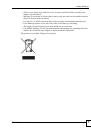
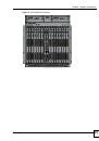
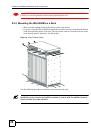
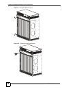
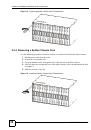
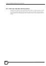
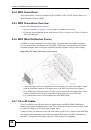
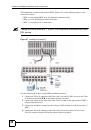
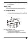
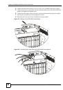
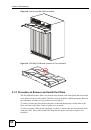
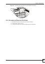
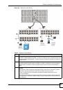
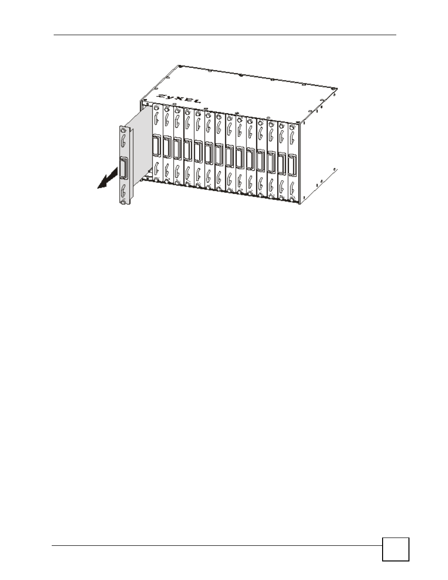
Figure 17
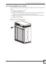
Removing a Splitter Chassis Card
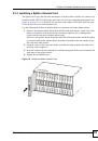
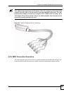
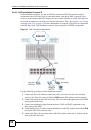
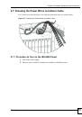
2.4 Making Card Connections
The following describes how to connect the line cards to the splitter chassis cards. For the
management switch card, refer to the card’s User’s Guide for instructions on making the
connections.
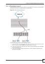
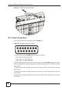
Use a Telco-50 cable to connect the line card’s front panel Telco-50 connector to the
corresponding splitter or extension card’s front panel Telco-50 connector. Make sure that you
use the appropriate length Telco-50 cables with the line cards, as using cables of the wrong
length blocks access to other cards. See
for the lengths of ZyXEL’s
optional Telco-50 cables.
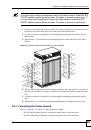
Cards are hot-swappable, so make sure cables do not obstruct insertion and removal of cards.
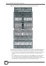
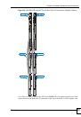
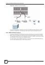
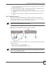
Follow these directions if there is one splitter chassis below the IES-6000M main chassis.
• Use a short Telco-50 cable to connect a line card’s
25-48
Telco-50 connector to the Telco-
50 connector on the corresponding splitter or extension card.
• Use a medium Telco-50 cable to connect a line card’s
1-24
Telco-50 connector to the
Telco-50 connector on the corresponding splitter or extension card.
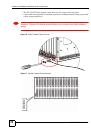
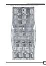
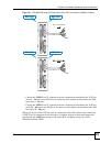
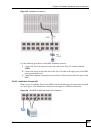
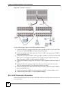
Follow these directions if there are two splitter chassis below the IES-6000M main chassis.
• Use a short Telco-50 cable to connect a line card’s
25-48
Telco-50 connector to the Telco-
50 connector on the corresponding splitter card of the upper splitter chassis.
• Use a medium Telco-50 cable to connect a line card’s
1-24
Telco-50 connector to the
Telco-50 connector on the corresponding splitter card of the lower splitter chassis.