Chapter 2 Hardware Installation and Connections
IES-6000M User’s Guide
50
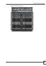
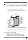
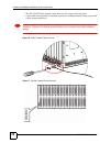
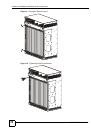
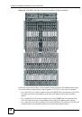
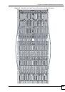
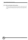
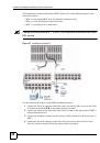
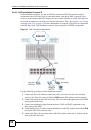
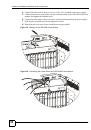
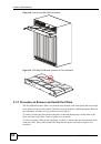
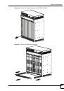
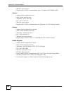
Figure 29
Installation Scenario C
Use the following procedure for this MDF installation scenario.
1
Connect the Telco-50 connector end of the cable you want for DSL service to the Telco-
50 connector labeled
USER
on the splitter chassis rear panel.
2
Connect the wiring on the other side of the Telco-50 cable to the upper ports of MDF 3
using a punch-down tool.
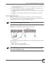
3
Connect the lower ports of MDF 3 to the upper ports of MDF 2 for those users that want
DSL service. (Users who want telephone service only, retain the original connection
from the top port of MDF 2 to the bottom port of MDF 1.)
4
Connect the telephone wiring from the end-user’s DSL equipment to the lower ports of
MDF 2.
5
Connect the Telco-50 connector end of the cable you want for phone service to the
Telco-50 connector labeled CO on the splitter chassis rear panel.
6
Connect the wiring on the other side of the Telco-50 cable to the lower ports of MDF 4
using a punch-down tool.
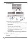
7
Connect the top ports of MDF 4 to the bottom ports of MDF 1 using telephone wires.
8
Connect the top ports of MDF 1 to the telephone company.
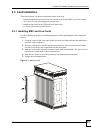
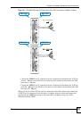
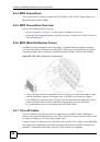
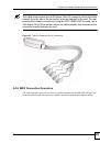
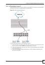
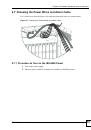
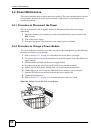
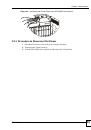
2.4.9 VoIP Connection Scenarios
These scenarios describe how to use the VOP1248G VoIP line card to provide voice service to
your subscribers.