Chapter 2 Hardware Installation and Connections
IES-6000M User’s Guide
54
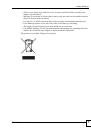
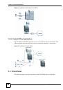
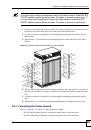
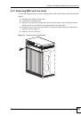
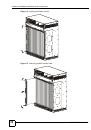
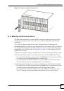
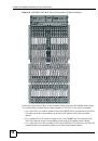
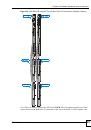
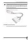
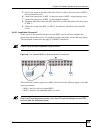
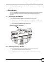
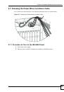
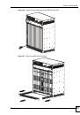
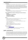
Figure 33
Removing the Alarm Module
2.5.3 Alarm Connections
This section explains the connections to the
ALARM
port.
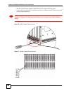
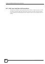
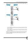
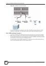
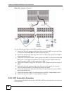
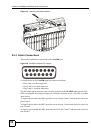
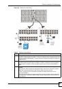
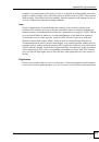
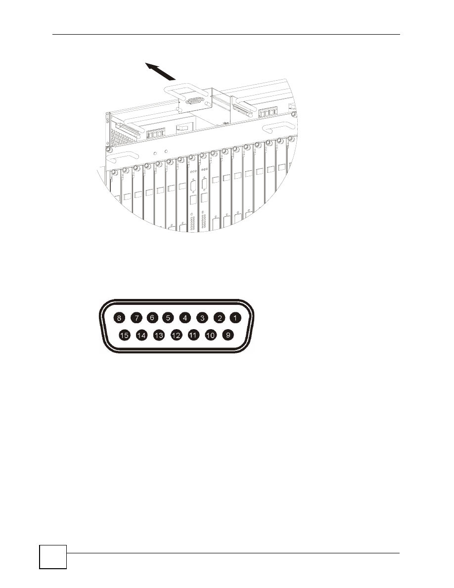
Figure 34
ALARM Connector Pin Layout
A closed circuit on the
ALARM
input pins indicates an alarm.
• Pins 1 and 9 are alarm input one.
• Pins 2 and 10 are alarm input two.
• Pins 3 and 11 are alarm input three.
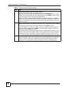
The IES-6000 signals an alarm when it detects an alarm on the
ALARM
input pins, the IES-
6000 is overheated, the voltage readings are outside the tolerance levels, a fan fails, or another
alarm occurs.
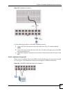
To signal a minor alarm, the MSC opens the circuit for pins 4 and 12 and closes the circuit for
pins 5 and 12.
To signal a major alarm, the MSC opens the circuit for pins 13 and 6 and closes the circuit for
pins 14 and 6.
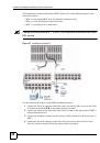
To signal a critical alarm, the MSC opens the circuit for pins 7 and 15 and closes the circuit for
pins 8 and 15.