Chapter 2 Hardware Installation and Connections
IES-6000M User’s Guide
55
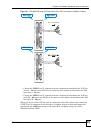
2.6 Power Connections
Use the following procedures to connect the IES-6000 to a power source after you have
installed the main chassis in a rack.
1
Refer to
for power requirements and make sure you
are using an appropriate power source.
Observe the following before you start:
• Refer to
for the gauge of wire to use for the IES-6000 power
connections.
• Keep the IES-6000 power switches in the
OFF
position until you come to procedure for
turning on the power.
• Keep the power supply switch in the
OFF
position until you come to procedure for turning
on the power.
1
Use only power wires of the required diameter for connecting the IES-6000 to
a power supply (refer to
for the required wire gauge).
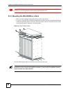
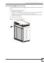
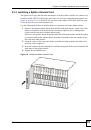
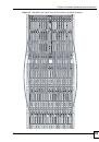
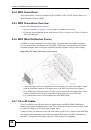
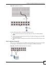
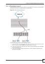
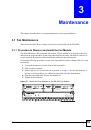
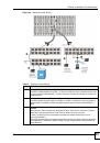
2.6.1 Power Modules
The main chassis uses two power supply modules. These modules are hot-swappable and
supply power to the line cards.
The power connections are on the front of each power module. The power modules are in the
upper left and upper right corners of the front panel of the main chassis.
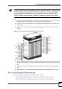
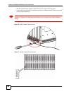
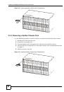
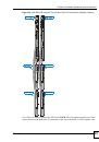
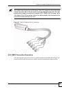
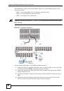
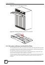
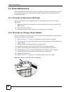
2.6.1.1 Procedure to Connect the Power
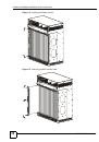
1
When installing the IES-6000 power wires, push the wires firmly into the
terminals as deep as possible and make sure that no exposed (bare) wires
can be seen or touched.
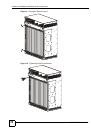
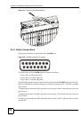
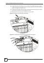
Use four wires to connect to each power module, two wires for the positive terminals and two
wires for the negative terminals.
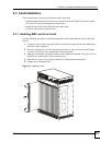
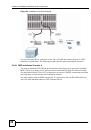
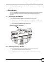
1
Use a screwdriver to loosen the power module screws.
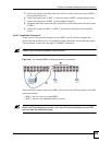
2
Slide the power module out partially to expose the power terminal screws.
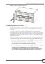
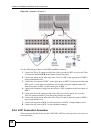
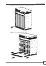
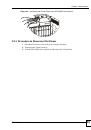
3
Connect power wires to the negative power terminals on the front of the power module,
and tighten the terminal screw.