List of Figures
IES-6000M User’s Guide
15
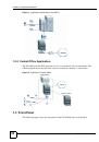
Figure 1 Application: Multi-tenant Unit (MTU) ........................................................................................ 22
Figure 2 Application: Central Office ........................................................................................................ 22
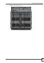
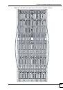
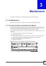
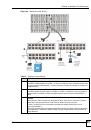
Figure 3 IES-6000M Front Panel ............................................................................................................ 23
Figure 4 Main Chassis Airflow ................................................................................................................ 28
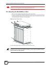
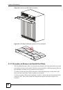
Figure 5 Attaching Mounting Brackets to the Main Chassis ................................................................... 29
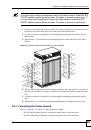
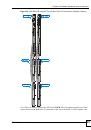
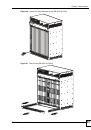
Figure 6 Main Chassis Frame Ground ................................................................................................... 30
Figure 7 Splitter Chassis Frame Ground ................................................................................................ 30
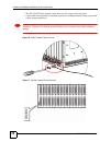
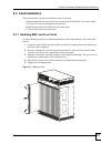
Figure 8 Installing a Card ....................................................................................................................... 31
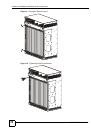
Figure 9 Closing the Ejector Levers ....................................................................................................... 32
Figure 10 Tightening Card Thumbscrews ............................................................................................... 32
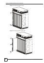
Figure 11 Loosening Card Thumbscrews ............................................................................................... 33
Figure 12 Opening the Ejector Levers .................................................................................................... 34
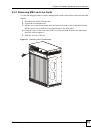
Figure 13 Removing a Main Chassis Card ............................................................................................. 34
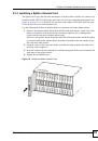
Figure 14 Installing a Splitter Chassis Card ............................................................................................ 35
Figure 15 Tightening Splitter Chassis Card Thumbscrews ..................................................................... 36
Figure 16 Loosening Splitter Chassis Card Thumbscrews ..................................................................... 36
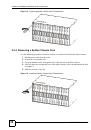
Figure 17 Removing a Splitter Chassis Card .......................................................................................... 37
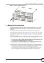
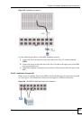
Figure 18 IES-6000 Front Panel Telco-50 Connections (2 Splitter Chassis) .......................................... 38
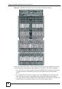
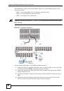
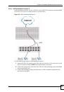
Figure 19 IES-6000 DSL and VoIP Front Panel Telco-50 Connections (2 Splitter Chassis) .................. 39
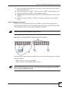
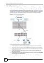
Figure 20 IES-6000 DSL and VoIP Rear Panel Telco-50 Connections (2 Splitter Chassis) ................... 41
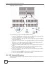
Figure 21 MDF (Main Distribution Frame) Wiring ................................................................................... 42
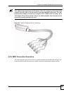
Figure 22 Telco-50 Cable with RJ-11 Connectors .................................................................................. 43
Figure 23 Installation Overview Example ............................................................................................... 44
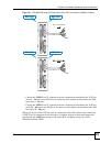
Figure 24 Installation Scenario A ............................................................................................................ 45
Figure 25 One MDF for End-user and CO Connections ......................................................................... 45
Figure 26 Installation Scenario B ............................................................................................................ 46
Figure 27 Two Separate MDFs for End-user and CO Connections ....................................................... 47
Figure 28 Installation Scenario C ........................................................................................................... 48
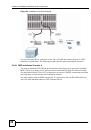
Figure 29 VoIP Connection Scenario A .................................................................................................. 49
Figure 30 VoIP Connection Scenario B .................................................................................................. 50
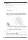
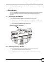
Figure 31 Installing the Alarm Module .................................................................................................... 51
Figure 32 Removing the Alarm Module .................................................................................................. 52
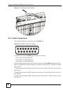
Figure 33 ALARM Connector Pin Layout .............................................................................................. 52
Figure 34 Sliding Out the IES-6000 Power Module ................................................................................ 54
Figure 35 Connecting the Power Wires to the IES-6000 Power Module ............................................... 54
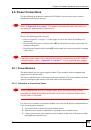
Figure 36 Dressing the Power Wires and Alarm Cable ........................................................................ 55
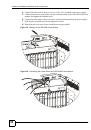
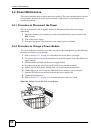
Figure 37 Loosen the Thumbscrews on the IES-6000 Fan Module ....................................................... 59
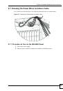
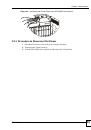
Figure 38 Remove the IES-6000 Fan Module ........................................................................................ 60